Movement Stories: Longines 19AS Automatic
As we continue our exporation of weird and wonderful automatic movements, let’s take a look at the 1950s-era Longines 19AS. The 19AS sits in a wonderfully in-between moment in automatic watchmaking—when the industry was leaving bumper automatics behind, but hadn’t yet settled on the now-familiar reversing wheel architecture that would dominate later full-rotor designs. In this article, we’ll walk through assembly of the 19AS automatic mechanism step by step, using the process not just as a repair guide but as a tour of the movement’s thinking: how Longines packaged a modern, 360° oscillating weight into a layout that still carries transitional DNA. Along the way we’ll highlight the design choices that make the 19AS such an interesting—and frankly underappreciated—milestone: a practical, serviceable full-rotor automatic that hints at the future while still wearing the fingerprints of the bumper age.
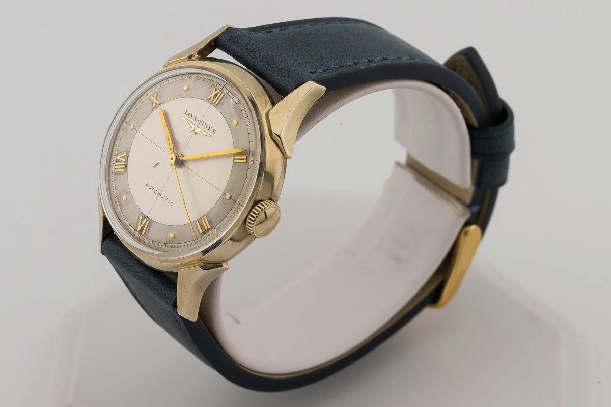
We’ll start our journey with the base movement already assembled, running, and lubricated:
The base movement design is a fairly typical 15 jewel layout with a center second pinion that is indirectly driven by an elevated 3rd wheel. There are a few interesting design features to note here:
The distribution of jewels in the train of wheels is somewhat unusual. The 3rd wheel uses a steel bushing on the dial side, which allows both the 3rd wheel and the center wheel to ride on jeweled bearings while the watch is in the common dial-up position, while maintaining a 17-jewel count for the full movement (with two jewels assigned to the automatic mechanism). This was an important consideration for US import watches, as anything over 17 jewels at the time would get hit with a substantially higher import tariff.
The barrel bridge is particularly tall and beefy, and the crown & ratches wheels, as well as the click, are deeply recessed in the bridge. This provides a solid structural base for the automatic mechanism, as we shall see.
The movement itself is actually rather compact, nestled into the middle of a wide base plate (dressed up with lovely perlage). This is needed to provide clearance for a fairly massive oscillating weight, which in turn is needed to provide sufficient torque to drive the automatic mechanism.
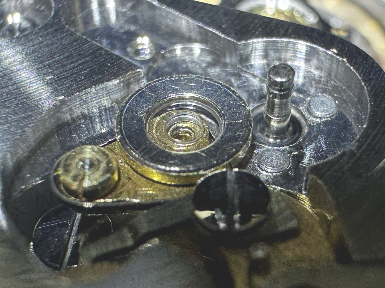
Note the jeweled pivot just to the right of the ratchet wheel, which will accept the pinion that transfers torque from the automatic mechanism. This is the 16th jewel in the movement.
Finally, note one more unusual feature, the tall post extending from the center of the crown wheel cover plate.
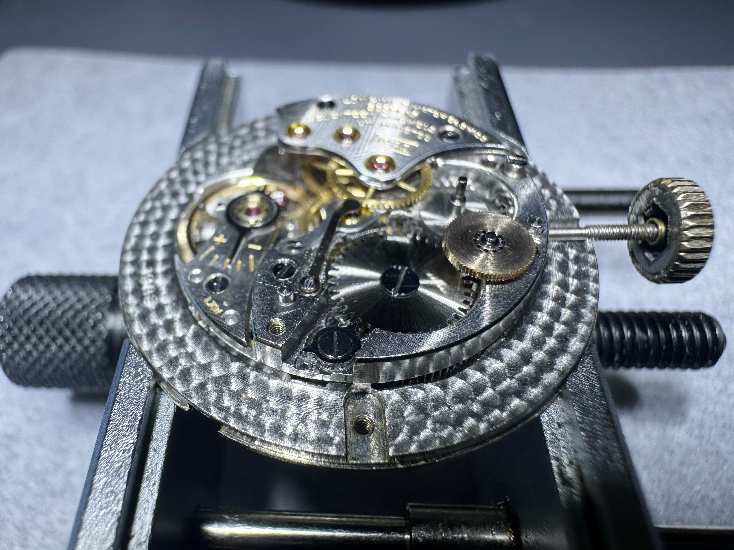
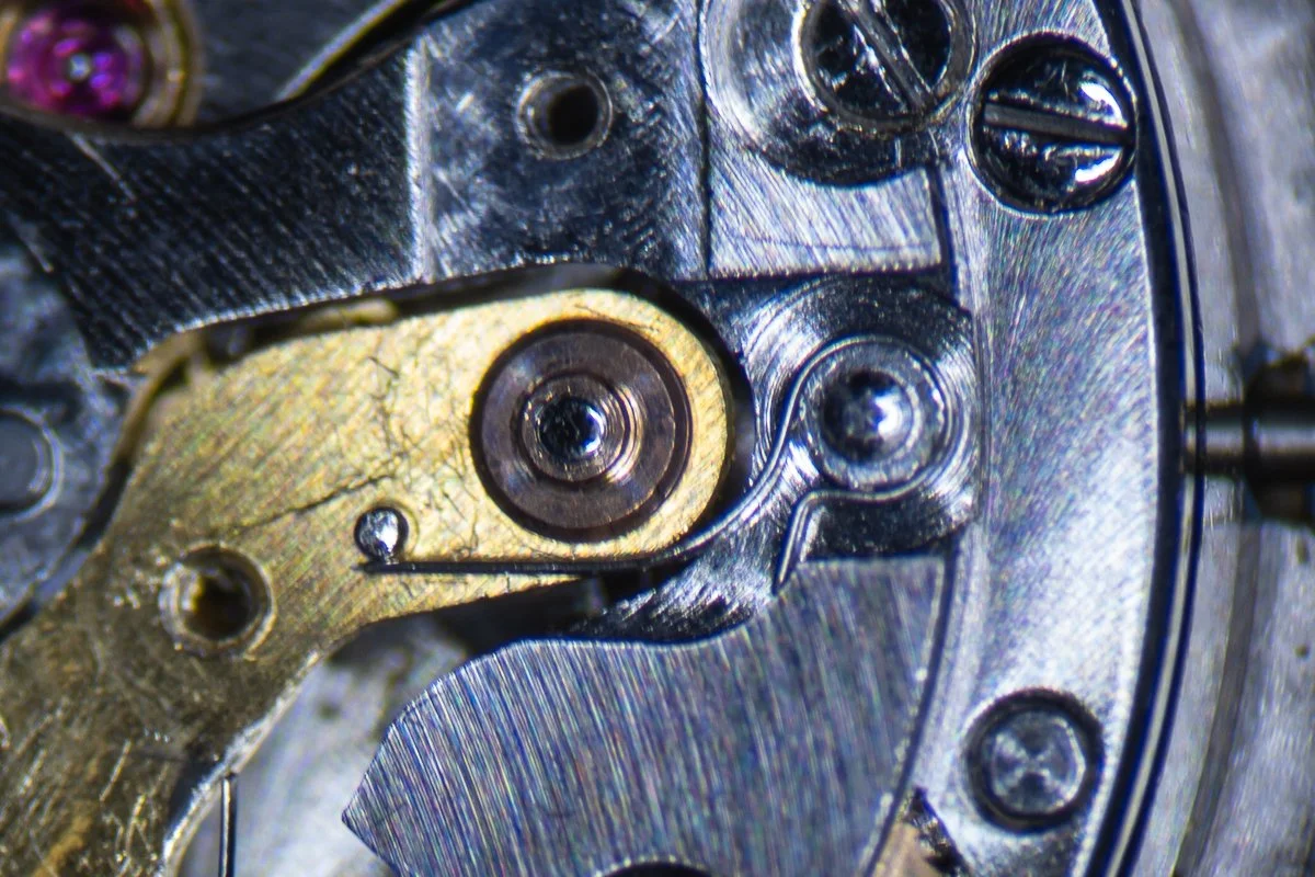
The pivot adjacent to the ratchet wheel accepts a driving wheel for the automatic mechanism, which you can see in the photo above. The design of this wheel, with its fine teeth, bears more than a passing resemblence to the driving wheels in typical bumper automatic movements, and this is no coincidence.
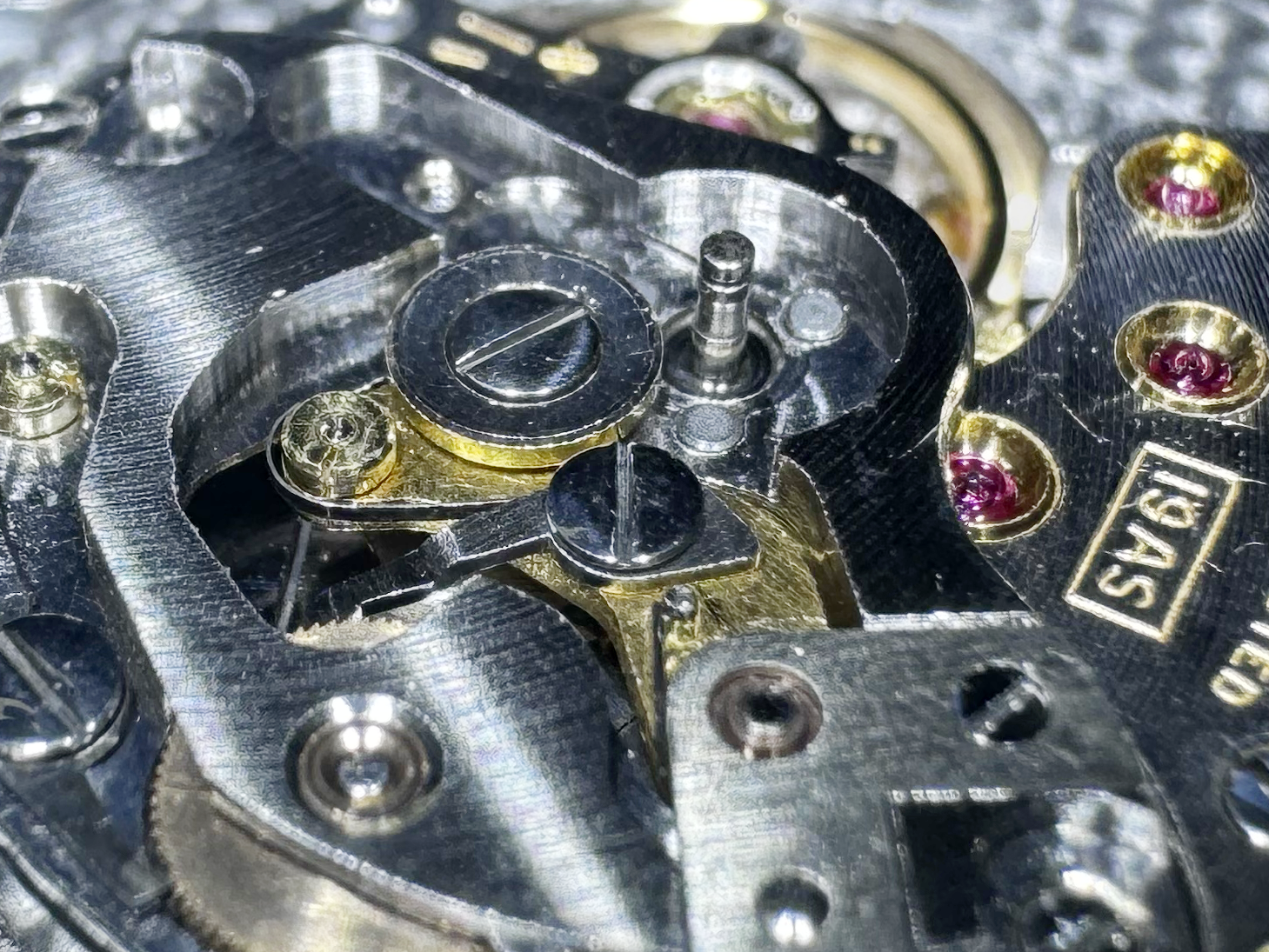
The upper pivot of the driving wheel is retained by a subtantial automatic bridge which screws onto the barrel bridge. At first, it might seem odd that the lower pivot of this wheel is jeweled, while the upper pivot sits in a simple bushing, but the lower pivot is subject to a substaintially higher torque load, so it actually makes a lot of sense. Notice that the pivot post attached to the crown wheel cover plate is tall enough to project up through this bridge.
The crown wheel post supports a brass rocker plate that fits neatly into the gap in the automatic bridge. I have to admit I’m not at all clear why Longines attached this post to the crown wheel cover plate instead of attaching it directly to or machining it into the automatic bridge, as this design makes it essentially impossible to remove the automatic works as a single unit. If you have a theory as to why it was done this way, leave a comment!
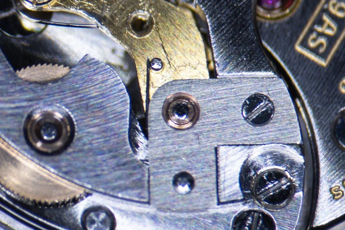
The rocker arm is engaged by a small tension spring, and then the entire arrangement is held in place by an L-shaped cover plate.
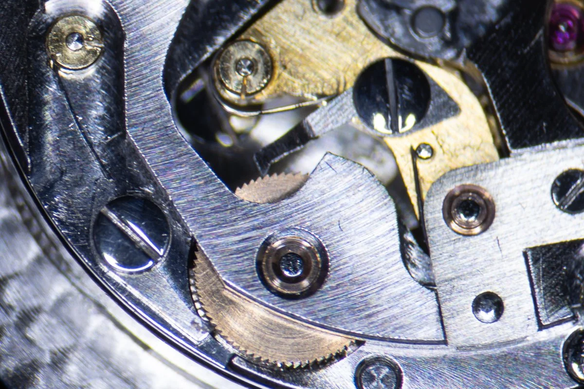
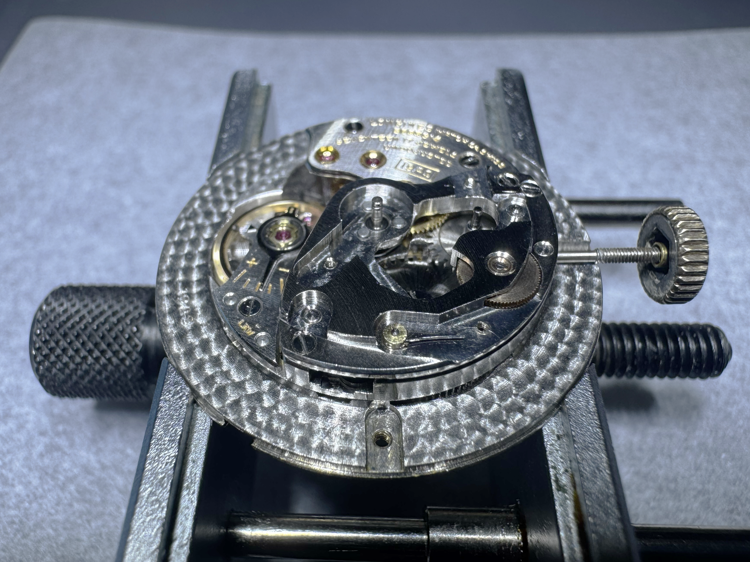
Winding is accomplished with the help of two pawls that engage the small teeth on the automatic driving wheel, as shown above. One of the pawls (toward the lower left) is fixed to the automatic bridge. It acts as a secondary click, allowing the only counter-clockwise motion of the driving wheel. The other pawl (toward the upper right) is attached to the rocker arm. When the rocker arm is rotated against its tension spring, this pawl pushes against the driving wheel, causing it to rotate and wind the watch. This process is illustrated in the video below:
Again, the mechanics at play here very much resemble the racheting mechanisms of contemporary bumper automatics, so the design lineage is clear. One interesting detail is that the tension springs for the pawls are mounted on press fit collets, similar to a hairspring collet. The nice thing about this is that the springs can be rotated out of the way while the pawls are bing installed, but unfortunately they can also get loose: I had to tighten the collet for the secondary click spring.
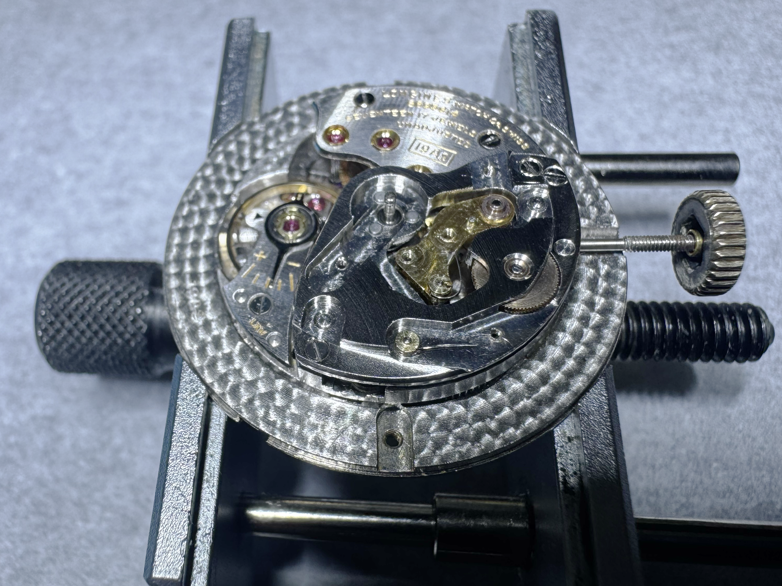
So, now the basics of the automatic drive are in place, but obviously the rocker arm ultimately needs to be driven by the oscillating weight, not my plastic pointer, so let’s see how that works…
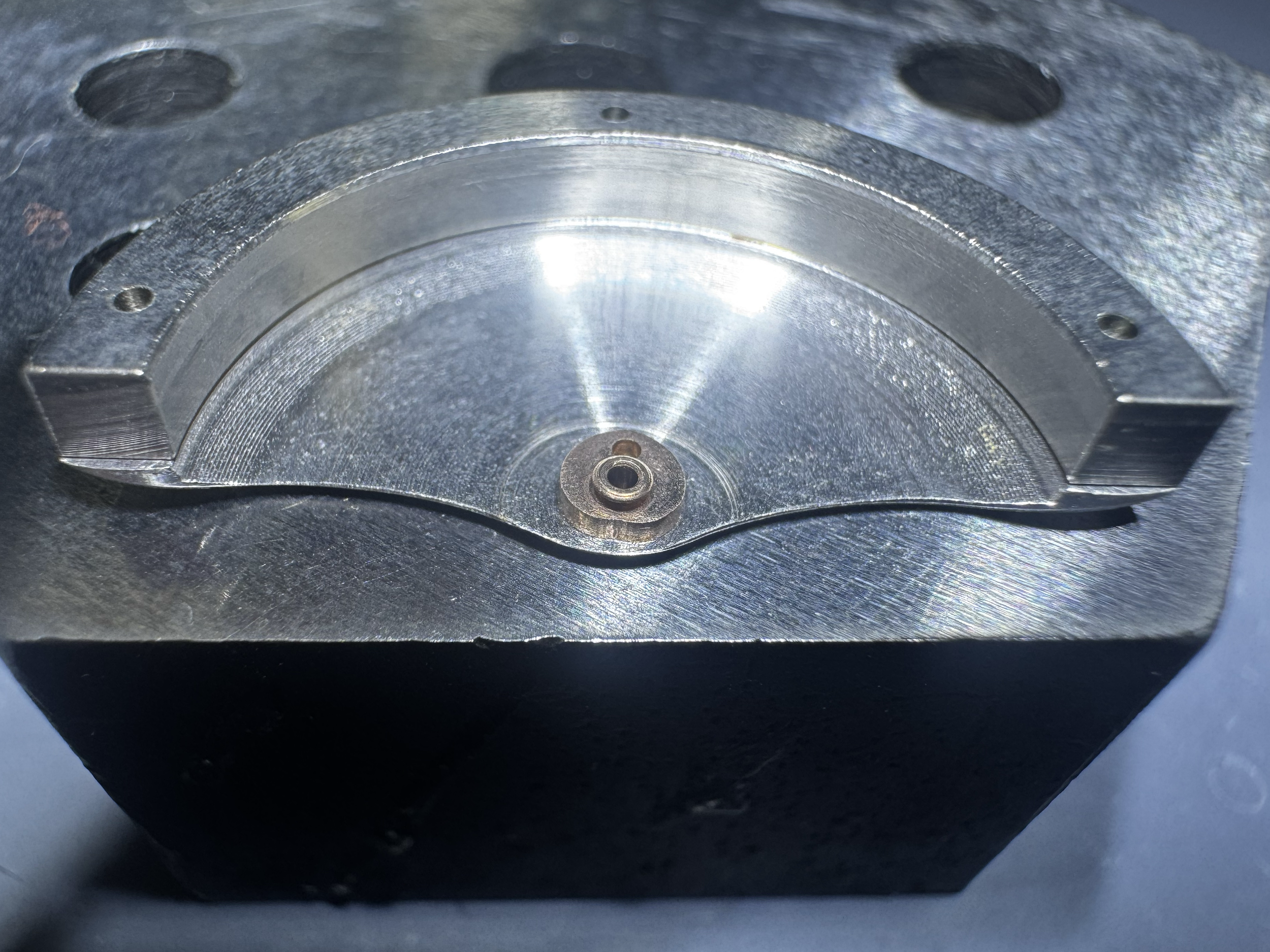
In this case, the “secret” is a small, heart shaped cam which fits around the pivot of the oscillating weight. This cam is ultimately what pushes on the rocker arm when the oscillating weight spins. By the way, check out how beefy this weight is - this winding mechanism is functional, but it requires a considerable amount of torque to work reliably. Hence the comparatively massive weight.
To minimize friction, the cam transfers torque to the rocker arm via a roller which screws to the arm. The center of the roller is jeweled to further minimize friction and wear - this is the 17th jewel of the movement. If you’re a car person, you’ll notice the similarity between this design and roller-rocker automotive cams.
All that remains is to install the oscillating weight on its post! Per my usual practice, I don’t install the weight until after the movement is cased up, as it tends to get in the way if installed beforehand:
And there you have it. It’s certainly not as efficient as later full-rotor automatic movements, but the 19AS is nonetheless a robust and clever attempt that marries design features of bumper automatics with a full 360 degree oscillating weight.
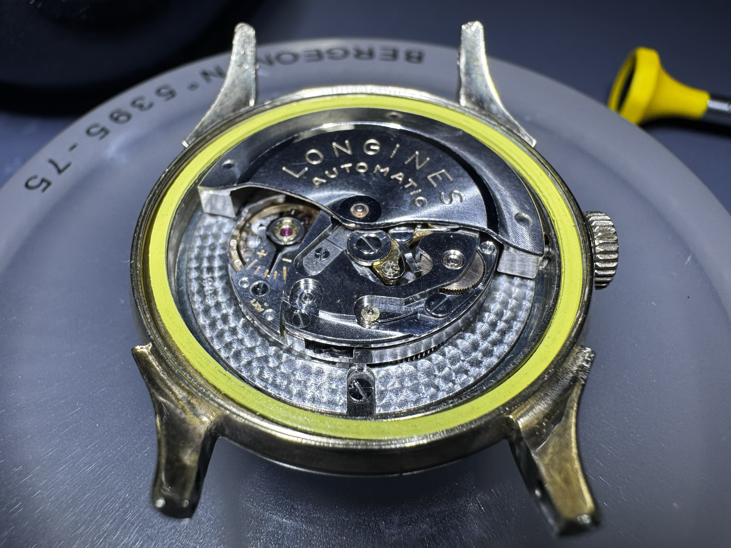
I’ll mention that this movement is housed in a beautiful 1952 Longines that is now part of my private collection: